
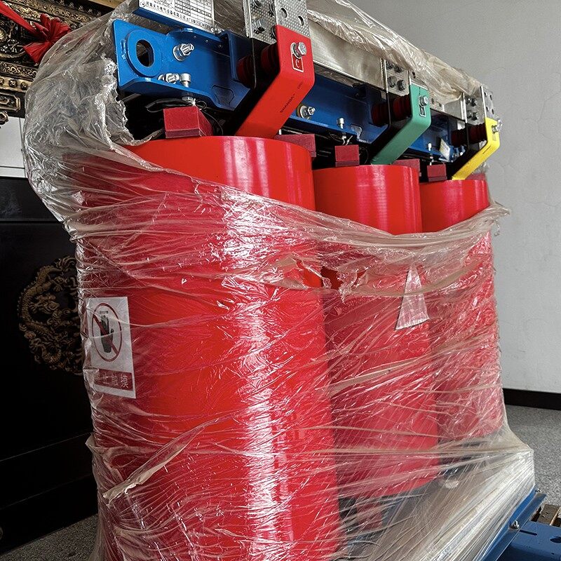
<h1 style="text-align: left;">Comprehensive Analysis of Future Development Directions and New Technical Requirements for Epoxy Resin Cast Dry-Type Transformers</h1><p</h1>
<p style="text-align: left;"><strong>Author: Dongguan DENSON Functional Materials Co., Ltd.</strong></p><hr><h2</strong></p>
<p style="text-align: left;"><strong>Date: 1</strong></p>
<h3 style="text-align: left;">1. Industry Background and Current Development</h3>
<p style="text-align: left;">Epoxy resin cast dry-type transformers (Cast Resin Transformers, CRT) have become the preferred choice for urban distribution networks, data centers, rail transit, and renewable energy grid integration due to their fire resistance, maintenance-free operation, moisture and contamination resistance, and flexible installation. In 2026, China's resin-cast dry-type transformer market is projected to reach 13.79 billion RMB, representing a year-over-year growth of 7.2%. Epoxy-cast products account for over 86%.</p><p% of this market.</p>
<p style="text-align: left;">However, the industry is undergoing a profound technological transformation. On one hand, <strong>GB 20052-2024 "Minimum Allowable Values of Energy Efficiency and Energy Efficiency Grades for Power Transformers"</strong> officially took effect on February 1, 2025. The "Distribution Transformer Energy Efficiency Improvement Plan (2024–2027)" mandates that all newly commissioned dry-type transformers from 2025 onward must meet at least SCB14 (Tier 2 energy efficiency). Coupled with overseas regulations like the EU EcoDesign Tier 3 Directive and US DOE new standards, rising energy efficiency thresholds are reshaping the competitive landscape. On the other hand, downstream demands—such as building new power systems, large-scale renewable energy integration, and expanding data center computing power—have imposed unprecedented requirements on transformer overload capacity, intelligence levels, and environmental adaptability.</p>
<p style="text-align: left;">This article systematically analyzes the future development directions and new technical requirements of epoxy resin cast dry-type transformers across six dimensions: <strong>energy efficiency improvement, material innovation, process upgrades, intelligent operations and maintenance, green low-carbon transition, and application expansion</strong>.</p>
<h3 style="text-align: left;">2. Energy Efficiency Improvement: Continuous Leap from SCB14 to Super Tier-1</h3>
<h4 style="text-align: left;">2.1 Evolution Path of Energy Efficiency</h4>
<p style="text-align: left;">China's dry-type transformer energy efficiency grades have continuously upgraded from SCB10 → SCB11 → SCB12 → SCB13 → SCB14 → SCB18. Following the implementation of GB 20052-2024, SCB14 (Tier 2 energy efficiency, NX2) has become the market access threshold, while SCB18 (Tier 1 energy efficiency, NX1) dominates the high-end market. Taking a 1250 kVA product as an example:</p>
<table style="min-width: 125px;"><colgroup><col; border-bottom-width: 1px;"><th; background-color: transparent; padding-inline-start: 8px;">
<thead>
<tr>
<th style="padding-inline-start: 8px;" colspan="1" rowspan="1">Performance Code</th>
<th style="padding-inline-start: 8px;" colspan="1" rowspan="1">Energy Efficiency Grade</th>
<th style="padding-inline-start: 8px;" colspan="1" rowspan="1">No-Load Loss (W)</th>
<th style="padding-inline-start: 8px;" colspan="1" rowspan="1">Load Loss (W)</th>
<th style="padding-inline-start: 8px;" colspan="1" rowspan="1">Energy Saving vs. SCB10</th>
</tr>
</thead>
<tbody>
<tr style="border-bottom-width: 1px;"><td; padding-inline-start: 8px; background-color: transparent;">
<td colspan="1" rowspan="1">SCB10</td>
<td colspan="1" rowspan="1">Obsolete</td>
<td colspan="1" rowspan="1">~420</td>
<td colspan="1" rowspan="1">~10,500</td>
<td colspan="1" rowspan="1">Baseline</td>
</tr>
<tr style="border-bottom-width: 1px;"><td; padding-inline-start: 8px; background-color: transparent;">
<td colspan="1" rowspan="1">SCB13</td>
<td colspan="1" rowspan="1">Tier 3</p></td><td</td>
<td colspan="1" rowspan="1">~340</td>
<td colspan="1" rowspan="1">~9,200</td>
<td colspan="1" rowspan="1">No-load -19%, Load -12%</td>
</tr>
<tr style="border-bottom-width: 1px;"><td; padding-inline-start: 8px; background-color: transparent;">
<td colspan="1" rowspan="1">SCB14</td>
<td colspan="1" rowspan="1">Tier 2</p></td><td</td>
<td colspan="1" rowspan="1">~280</td>
<td colspan="1" rowspan="1">~8,200</td>
<td colspan="1" rowspan="1">No-load -33%, Load -22%</td>
</tr>
<tr style="border-bottom-width: 1px;"><td; padding-inline-start: 8px; background-color: transparent;">
<td colspan="1" rowspan="1">SCB18</td>
<td colspan="1" rowspan="1">Tier 1</p></td><td</td>
<td colspan="1" rowspan="1">~200</td>
<td colspan="1" rowspan="1">~7,200</td>
<td colspan="1" rowspan="1">No-load -52%, Load -31%</td>
</tr>
</tbody>
</table>
<h4 style="text-align: left;">2.2 Large-Scale Application of Amorphous Alloy</h4>
<p style="text-align: left;">The core breakthrough for energy efficiency lies in the <strong>magnetic core material revolution</strong>. The iron loss of conventional grain-oriented silicon steel sheets (e.g., 30Q120) is approaching the physical limit, leaving little room for further no-load loss reduction. Amorphous alloy strips, with their long-range disordered atomic arrangement, exhibit extremely low hysteresis loss, achieving no-load losses that are <strong>60%–80% lower</strong> than equivalent silicon steel cores.</p>
<p style="text-align: left;">The SCBH15 series amorphous alloy dry-type transformers have achieved mass production, reducing no-load loss for 1250 kVA products to below 120 W. However, amorphous alloys present three major technical challenges:</p>
<ul>
<li><p style="text-align: left;"><strong>Thin strip thickness</strong> (approx. 25 μm, only 1/10 of standard silicon steel), resulting in a low stacking factor and a ~5–8%;</p></li><li><p% reduction in core fill factor;</p></li>
<li><p style="text-align: left;"><strong>Hard and brittle material</strong>, making shearing and stacking difficult and imposing strict requirements on manufacturing equipment and process control;</p></li>
<li><p style="text-align: left;"><strong>High magnetostriction coefficient</strong>, causing no-load noise 3–5 dB higher than silicon steel cores, necessitating optimized core structures and vibration damping designs.</p></li>
</ul>
<p style="text-align: left;"><strong>Future Outlook:</strong> Increasing domestic production rates of amorphous alloy strips (now matching international quality at costs ~20% lower than imports), core structure optimization (stepped lap joints, rectangular cross-sections), and integrated sound insulation will drive the penetration rate of amorphous dry-type transformers in the Tier 1 market from the current ~15% to over 40% by 2030.</p><h3.</p>
<h4 style="text-align: left;">2.3 Winding Structure Optimization and Load Loss Reduction</h4>
<p style="text-align: left;">Reducing load loss (copper loss) is primarily achieved through:</p>
<ul>
<li><p style="text-align: left;"><strong>Conductor material upgrade:</strong> High-purity copper (oxygen content ≤0.001%) replaces conventional copper, reducing resistivity by ~1–2%;</p></li><li><p%.</p></li>
<li><p style="text-align: left;"><strong>Winding structure optimization:</strong> Foil windings replace wire-wound windings. Low-voltage windings use copper foil (0.5–2.0 mm thick), providing better axial heat dissipation and reducing eddy current loss by ~15%;</p></li><li><p%.</p></li>
<li><p style="text-align: left;"><strong>Transposed conductor application:</strong> High-voltage windings use Continuously Transposed Conductors (CTC) to reduce additional losses from skin and proximity effects.</p></li>
<li><p style="text-align: left;"><strong>Electromagnetic simulation-driven design:</strong> Optimizing turns, wire diameter, and arrangement via Finite Element Analysis (FEA) minimizes copper loss while meeting impedance voltage and short-circuit impedance requirements.</p></li>
</ul>
<h3 style="text-align: left;">3. Material Innovation: Multi-Dimensional Upgrading of Epoxy Resin</h3>
<p style="text-align: left;">Epoxy resin is the core insulating material for cast dry-type transformers. Its performance dictates dielectric strength, thermal class, heat dissipation, and service life. Current epoxy systems are upgrading from conventional bisphenol-A toward <strong>high thermal conductivity, high heat resistance, low shrinkage, and environmentally friendly formulations</strong>.</p>
<h4 style="text-align: left;">3.1 High Thermal Conductivity Epoxy Systems: Breaking the Heat Dissipation Bottleneck</h4>
<p style="text-align: left;">Conventional epoxy resins have a thermal conductivity of only ~<strong>0.2 W/(m·K)</strong>, acting as typical thermal insulators. Heat generated during operation must conduct through the epoxy layer to the surface, where it is dissipated by air. Insufficient conductivity leads to high winding hot-spot temperatures, limiting overload capacity and power density.</p>
<p style="text-align: left;">High thermal conductivity epoxy systems create continuous conduction networks within the resin matrix using high-conductivity insulating fillers. Key technical routes include:</p>
<p style="text-align: left;"><strong>(1) Nano-SiO₂ Modified Systems</strong></p>
<p style="text-align: left;">Using surface-modified nano-silica particles (10–50 nm) bonded to the epoxy matrix via silane coupling agents (e.g., KH550). Nanoparticles form "thermal conduction network chains," increasing thermal conductivity to <strong>1.5–1.8 W/(m·K)</strong>, ~23% higher than conventional systems. In 2025, new resins using SiO₂ nano-modification already accounted for 23.7%.</p><p% of shipments.</p>
<p style="text-align: left;"><strong>(2) Hexagonal Boron Nitride (h-BN) Filled Systems</strong></p>
<p style="text-align: left;">h-BN features a graphene-like layered structure with in-plane thermal conductivity up to ~300 W/(m·K) and inherent electrical insulation. A synergistic filling strategy ("micron h-BN backbone + nano BN bridging") establishes main heat paths while nanoparticles fill gaps, achieving thermal conductivity of <strong>0.6–0.8 W/(m·K)</strong> (> 200% increase vs. pure epoxy). h-BN systems maintain good castability with minimal viscosity impact.</p>
<p style="text-align: left;"><strong>(3) Alumina (Al₂O₃)/Metal Hybrid Systems</strong></p>
<p style="text-align: left;">Using Al₂O₃-SnBi hybrid fillers can reach <strong>2.95 W/(m·K)</strong> at 60% filler volume. However, high viscosity makes casting difficult; currently used mainly in special scenarios like solid-state transformer (SST) power module potting.</p>
<p style="text-align: left;"><strong>Engineering Value:</strong> For a 2000 kVA dry-type transformer, adopting high thermal conductivity epoxy (1.8 W/(m·K)) reduces winding hot-spot temperature rise by ~15–20 K. Under Class F insulation (max temp rise 100 K), this enables ~20% improved overload capacity or ~15% higher power density at the same temperature rise, achieving miniaturization and weight reduction.</p>
<h4 style="text-align: left;">3.2 High Heat Resistance Epoxy Systems: Leap from Class F to Class H</h3><p</h4>
<p style="text-align: left;">Most conventional cast dry-type transformers use Class F insulation (max operating temp 155°C, max temp rise 100 K). With growing demands for overload capacity and compactness in data centers and renewable energy applications, <strong>Class H insulation systems</strong> (max operating temp 180°C, max temp rise 125 K) are accelerating adoption. Between 2023 and 2025, ~38% of new cast dry-type transformer models adopted Class H systems, enabling continuous operation up to 180°C and improving overload tolerance by ~15%.</p><p%.</p>
<p style="text-align: left;"><strong>Key Technologies for Class H Systems:</strong></p>
<ul>
<li><p style="text-align: left;"><strong>Cycloaliphatic epoxy resins:</strong> Replacing bisphenol-A benzene rings with cycloaliphatic structures raises Heat Deflection Temperature (HDT) above 155°C, offering excellent UV resistance and weatherability for outdoor/high-temp environments.</p></li>
<li><p style="text-align: left;"><strong>Anhydride curing agent optimization:</strong> Using high-temp resistant agents like methyl nadic anhydride (MNA) and hexahydrophthalic anhydride (HHPA) with accelerators to precisely control curing rates.</p></li>
<li><p style="text-align: left;"><strong>Glass Transition Temperature (Tg) improvement:</strong> Class H systems require Tg > 170°C to ensure sufficient mechanical strength and insulation at maximum operating temps.</p></li>
</ul>
<h4 style="text-align: left;">3.3 Low Shrinkage, Low Stress Epoxy Formulations</h4>
<p style="text-align: left;">Epoxy resins typically shrink 2–5% during curing. Internal stress from shrinkage can cause conductor displacement, insulation cracking, and reduced partial discharge inception voltage. Large-capacity, high-voltage products urgently require low-shrinkage epoxy.</p>
<p style="text-align: left;"><strong>Technical Directions:</strong></p>
<ul>
<li><p style="text-align: left;"><strong>Reactive diluent optimization:</strong> Using low-viscosity reactive diluents like butyl glycidyl ether (501) and 1,4-butanediol diglycidyl ether (622) to reduce system viscosity while minimizing curing shrinkage.</p></li>
<li><p style="text-align: left;"><strong>Toughening modification:</strong> Adding tougheners such as carboxyl-terminated butadiene-acrylonitrile rubber (CTBN) and core-shell rubber (CSR) to improve fracture toughness and absorb curing stress.</p></li>
<li><p style="text-align: left;"><strong>Inorganic filler grading:</strong> Using graded fillers (e.g., micron SiO₂ + nano SiO₂) to increase packing density, reduce resin phase proportion, and lower overall shrinkage.</p></li>
</ul>